Rleg  2
 All Data Structures Files Functions Variables Typedefs Macros Groups Pages
Functions
Functions for Gyrometer ITG3200
Collaboration diagram for Functions for Gyrometer ITG3200:

Functions

int gyr_write_reg (int i2c_dev, uint8_t reg, uint8_t data)
 WRITE TO REGISTER. More...
 
uint8_t * gyr_read_reg (int i2c_dev, uint8_t reg, uint8_t count)
 READ COUNT 8-BIT REGISTER IN SEQUENCE. More...
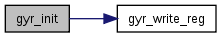
 
int gyr_init (int i2c_dev, float rate, short int lpf_bw, char clk_source, char *act)
 INITIALIZE GYROMETER. More...
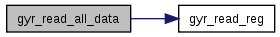
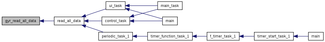
 
int gyr_read_all_data (int i2c_dev, short int *data)
 READ ALL DATA AT ONCE (X, Y, Z and T) More...
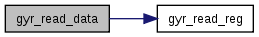
 
short int gyr_read_data (int i2c_dev, int type)
 READ DATA (X, Y, Z or T) More...
 

Detailed Description

Function Documentation

int gyr_init ( int  i2c_dev,
float  rate,
short int  lpf_bw,
char  clk_source,
char *  act 
)

INITIALIZE GYROMETER.

Parameters
lpf_bw(low pass filter bandwidth in Hz) = 256, 188, 98, 42, 20, 10 or 5
rate(output data rate in Hz) <= 1000 (Fint), if lpf_bw is not 256 <= 8000 (Fint), if lpf_bw is 256 Real rate will be the closest superior rate possible, respcting the formula Rate = Fint/n, 1<=n<=255
clk_source= 'I' Internal oscillator 'X' PLL with X Gyro reference 'Y' PLL with Y Gyro reference 'Z' Pll with Z Gyro reference Obs: It is highly recommended that the device is configured to use one of the gyros as the clock reference, due to the improved stability
act(activated gyro data) = "XYZ" All axes are activated "YZ" Only Y and Z axes are activated "XZ" Only X and Z axes are activated "XY" Only X and Y axes are activated "X" Only X axis is activated "Y" Only Y axis is activated "Z" Only Z axis is activated "" Device in very low power sleep mode
Returns
Data of register or NULL in case of any trouble

Definition at line 53 of file gyr_functions.c.

References GYR_DLPF_FS, GYR_PWR_MGM, GYR_SMPLRT_DIV, and gyr_write_reg().

Referenced by devices_init().

54 {
55  uint8_t data=0;
56  float Fint=1000;
57 
58  switch(lpf_bw){
59  case 256:
60  Fint=8000;
61  data=0x18;
62  break;
63  case 188:
64  data=0x19;
65  break;
66  case 98:
67  data=0x1A;
68  break;
69  case 42:
70  data=0x1B;
71  break;
72  case 20:
73  data=0x1C;
74  break;
75  case 10:
76  data=0x1D;
77  break;
78  case 5:
79  data=0x1E;
80  break;
81  default:
82  perror("Wrong low pass filter bandwidth value");
83  break;
84  }
85 
86  if(gyr_write_reg(i2c_dev, GYR_DLPF_FS, data)<0){
87  perror("Write in Configuration register A unsuccesful");
88  return -1;
89  }
90 
91  if( (rate>Fint)||(rate<0) )
92  {
93  perror("Wrong choice for rate");
94  return -1;
95  }
96  data=(uint8_t)(Fint/rate - 1);
97 
98  if(gyr_write_reg(i2c_dev, GYR_SMPLRT_DIV, data)<0){
99  perror("Write in configuration register B unsuccesful");
100  return -1;
101  }
102 
103  switch(clk_source){
104  case 'I':
105  data=0x00;
106  break;
107  case 'X':
108  data=0x01;
109  break;
110  case 'Y':
111  data=0x02;
112  break;
113  case 'Z':
114  data=0x03;
115  break;
116  default:
117  perror("Wrong clk_source value");
118  break;
119  }
120 
121  if( strcmp(act,"XYZ")==0 );
122  else if( strcmp(act,"YZ")==0 )
123  data=data|0x20;
124  else if( strcmp(act,"")==0 )
125  data=data|0x40;
126  else if( strcmp(act,"Y")==0 )
127  data=data|0x28;
128  else if( strcmp(act,"Z")==0 )
129  data=data|0x30;
130  else if( strcmp(act,"X")==0 )
131  data=data|0x18;
132  else if( strcmp(act,"XY")==0 )
133  data=data|0x08;
134  else if( strcmp(act,"XZ")==0 )
135  data=data|0x10;
136  else{
137  perror("Wrong act value in gyrometer initialization");
138  return -1;
139  }
140 
141  if(gyr_write_reg(i2c_dev, GYR_PWR_MGM, data)<0){
142  perror("Write in mode register unsuccesful");
143  return -1;
144  }
145 
146  return 1;
147 }
#define GYR_SMPLRT_DIV
Definition: imu_regs.h:47
#define GYR_PWR_MGM
Definition: imu_regs.h:59
int gyr_write_reg(int i2c_dev, uint8_t reg, uint8_t data)
WRITE TO REGISTER.
Definition: gyr_functions.c:10
#define GYR_DLPF_FS
Definition: imu_regs.h:48

Here is the call graph for this function:

Here is the caller graph for this function:

int gyr_read_all_data ( int  i2c_dev,
short int *  data 
)

READ ALL DATA AT ONCE (X, Y, Z and T)

Parameters
i2c_dev
[out]*dataVector with all data
Returns
Flag with SUCCESS or FAILURE

Definition at line 149 of file gyr_functions.c.

References FAILURE, gyr_read_reg(), GYR_TEMP_OUT_H, and SUCCESS.

Referenced by read_all_data().

150 {
151  uint8_t i;
152  uint8_t *data8;
153  union result
154  {
155  unsigned short int usgnd[4];
156  int short sgnd[4];
157  } result;
158  if( (data8=gyr_read_reg(i2c_dev,GYR_TEMP_OUT_H,8))==NULL)
159  {
160  //perror("Read accelerometer register failed");
161  return FAILURE;
162  }
163  // Result receives gyro data:
164  for(i=1; i<4; i++)
165  {
166  result.usgnd[i-1]=0;
167  result.usgnd[i-1]=result.usgnd[i-1]|((unsigned short int)data8[i*2+1])|(((unsigned int)data8[i*2])<<8);
168  data[i-1]=result.sgnd[i-1];
169  }
170  // Result receives temperature data:
171  result.usgnd[3]=0;
172  result.usgnd[3]=result.usgnd[3]|((unsigned short int)data8[1])|(((unsigned int)data8[0])<<8);
173  data[3]=result.sgnd[3];
174  return SUCCESS;
175 }
#define FAILURE
Definition: calibration.h:7
#define SUCCESS
Definition: calibration.h:6
uint8_t * gyr_read_reg(int i2c_dev, uint8_t reg, uint8_t count)
READ COUNT 8-BIT REGISTER IN SEQUENCE.
Definition: gyr_functions.c:31
#define GYR_TEMP_OUT_H
Definition: imu_regs.h:51

Here is the call graph for this function:

Here is the caller graph for this function:

short int gyr_read_data ( int  i2c_dev,
int  type 
)

READ DATA (X, Y, Z or T)

Parameters
i2c_dev
typeDefine kind of read: 'X' or 'Y' or 'Z' or 'T'(temperature)
Returns
Data

Definition at line 177 of file gyr_functions.c.

References GYR_GYRO_XOUT_H, GYR_GYRO_YOUT_H, GYR_GYRO_ZOUT_H, gyr_read_reg(), and GYR_TEMP_OUT_H.

178 {
179  uint8_t *data;
180  union result
181  {
182  unsigned int usgnd;
183  int sgnd;
184  }result;
185 
186  switch(type){
187  case 'X':
188  data=gyr_read_reg(i2c_dev,GYR_GYRO_XOUT_H,2);
189  break;
190  case 'Y':
191  data=gyr_read_reg(i2c_dev,GYR_GYRO_YOUT_H,2);
192  break;
193  case 'Z':
194  data=gyr_read_reg(i2c_dev,GYR_GYRO_ZOUT_H,2);
195  break;
196  case 'T':
197  data=gyr_read_reg(i2c_dev,GYR_TEMP_OUT_H,2);
198  default:
199  //perror("Wrong argument for type in gyr_read_data");
200  return -1;
201  }
202  result.usgnd=0;
203  result.usgnd=result.usgnd|(((unsigned short int)data[1]))|(((unsigned short int)data[0])<<8);
204  return result.sgnd;
205 }
#define GYR_GYRO_XOUT_H
Definition: imu_regs.h:53
#define GYR_GYRO_YOUT_H
Definition: imu_regs.h:55
#define GYR_GYRO_ZOUT_H
Definition: imu_regs.h:57
uint8_t * gyr_read_reg(int i2c_dev, uint8_t reg, uint8_t count)
READ COUNT 8-BIT REGISTER IN SEQUENCE.
Definition: gyr_functions.c:31
#define GYR_TEMP_OUT_H
Definition: imu_regs.h:51

Here is the call graph for this function:

uint8_t* gyr_read_reg ( int  i2c_dev,
uint8_t  reg,
uint8_t  count 
)

READ COUNT 8-BIT REGISTER IN SEQUENCE.

Parameters
regRegister
countnumber of registers in sequence
Returns
flag with SUCCESS or FAILURE
Todo:
Verify use of reg parameter

Definition at line 31 of file gyr_functions.c.

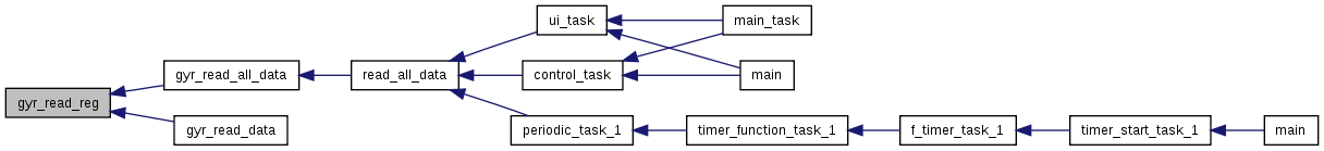
Referenced by gyr_read_all_data(), and gyr_read_data().

32 {
33  uint8_t data[9];
34  int i;
35 
36  //data=(uint8_t*)malloc((count+1)*sizeof(data));
37 
38  data[0] = reg;
39 
40  if (write(i2c_dev, &data, 1) != 1) {
41  //perror("write before read");
42  return NULL;
43  }
44  data[0] = 0;
45  if (read(i2c_dev, &data, count) != count) {
46  //perror("read");
47  return NULL;
48  }
49 
50  return data;
51 }

Here is the caller graph for this function:

int gyr_write_reg ( int  i2c_dev,
uint8_t  reg,
uint8_t  data 
)

WRITE TO REGISTER.

Parameters
i2c_dev
regRegister
dataData to write in Register
Author
Caio Gustavo Mesquita Ângelo Rev 0 - 12/11/2012 RLEG project - 2012

Implements the I2C communication between Gumstix Overo Fire and ITG3200

Definition at line 10 of file gyr_functions.c.

References FAILURE, GYR_INT_CFG, GYR_PWR_MGM, GYR_SMPLRT_DIV, GYR_WHO_AM_I, and SUCCESS.

Referenced by gyr_init().

11 {
12  uint8_t reg_data[2];
13 
14  reg_data[0] = reg;
15  reg_data[1] = data;
16 
17  if( !( (reg==GYR_WHO_AM_I)||((GYR_SMPLRT_DIV<=reg)&&(reg<=GYR_INT_CFG))||(reg==GYR_PWR_MGM) ) )
18  {
19  //perror("Write unsucessful: Not a valid writable register");
20  return FAILURE;
21  }
22 
23  if (write(i2c_dev, &reg_data, 2) != 2) {
24  //perror("Write unsuccessful");
25  return FAILURE;
26  }
27 
28  return SUCCESS;
29 }
#define GYR_SMPLRT_DIV
Definition: imu_regs.h:47
#define GYR_PWR_MGM
Definition: imu_regs.h:59
#define FAILURE
Definition: calibration.h:7
#define GYR_WHO_AM_I
Definition: imu_regs.h:46
#define GYR_INT_CFG
Definition: imu_regs.h:49
#define SUCCESS
Definition: calibration.h:6

Here is the caller graph for this function: